Magic damp reducing air bricks
By: admin | Posted on: December 8, 2020
A review and opinion of performance data relating to an environmentally controlled damp-proofing system.
1. INTRODUCTION:
In recent years there has been some significant advertising in the national press about a Patented, damp proofing system developed in Europe. Advertisements claim that it will effectively cure rising damp, condensation and penetrating damp. Similar claims are to be found on the Internet.

A European Patent was granted for the units. The Patent (EP 0 829 587 B1) describes the units in full and claims the units to be “Improved device to abstract moisture from a wall or similar, —-“: the patent then continues to describe the improvements.
The websites for the system describe it as, “– a humidity regulated system which consists of a stone element and a ceramic tube. The whole system is fixed in a specially prepared niche in the outside wall. Through an opening in the element, dry air can flow into the system. This is led directly in to the ceramic tube and two air chambers. The second opening in the system causes a draft. This leads to a drop in temperature within the tube and as a result a cold bridge is created. Since humidity tends to form at the coldest spot, it will gather in the ceramic tube from where it is transported out side by the air flow. In the same way, condensation from within the house also disappears.”
1.1 Construction:

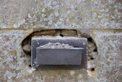
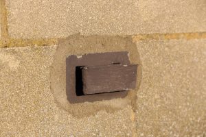
The element as removed from a solid wall appears to consist of a cast ‘stone’ hollow external rectangular element measuring approximately 115mm x 65mm x 40mm deep.

A similar cast ‘stone’ square ‘bell’ is fixed in the centre by some type of adhesive; this leaves two small air slots at either side of the ‘bell’. (see photos). A thick plastic card is then adhesived into a slot at the rear of the ‘bell’. The structure is cemented into a simple slot cut into the wall with the plastic piece forming and making the centre of the 2 chambers as described, ie, the plastic simply divides the hole cut into the wall for unit’s insertion. The protruding part of the ‘bell’ is proud of the wall surface.
A number of the websites refer to an evaluation of the system undertaken by the well respected independent Dutch Laboratory, TNO (Organisation for Applied Scientific Research) in support of performance, and it is to this and their finding that this review and opinion is directed.
2. TNO REPORT DATED 4TH APRIL 1985
As part of the “Introduction” it states, “–is a piece of equipment which, when installed in the wall is intended to remove (excess) moisture with the help of the surrounding air that flows along the wall.” It further states, “To gain a better understanding of how the system works two arrangements were set up. A wall simulation with variable air speeds and variable blowing angles was used to measure the air speed at the inlet and outlet apertures as well as atmospheric pressure on the blowing plane in the system. The bricks were placed in a plastic housing. Over a period of 12 weeks comparative measurements were carried out on two identical test walls. In one wall the system had been installed. During this test the moisture consumption and the relative humidity in and behind the cavity wall were measured whilst the air speed and the blowing angle remained constant.”
Under section 2.2, ‘Measuring results’ a discussion of the results in relation to the blowing angle are given and it states, inter alia, “This shows quite clearly that the selected wind speeds of 4, 5 and 6 m/s[approximately 8 – 12 mph] the largest air displacement in the system can be achieved within a blowing angle of 30° with an optimum value of 10°.”
In Section 3 ‘Comparative measurements’ it states,
“In addition to the preparatory measurements, which are needed to explain that the way the system operates, the performance of the system was studied in greater detail in the second test arrangement. In the main this was limited to matters such as water displacement and the influence of the system on relative humidity inside and behind the cavity wall
Because it is to be expected that this is a slow process it was decided to carry out the test under the most favourable conditions possible. In doing so, it was found that when the blowing angle was 10° and the airflow had a speed of 4 m per second the system had its greatest flow rate. The atmospheric pressure, too, reached a favourable value when this angle and speed were used.”
It continues, inter-alia “Because there is a moisture barrier in the cavity wall and over the base in the spaces above can be kept free from freely evaporating moisture. This means that the moisture can only travel upwards through the walls. By insulating the cavity and the space behind it was possible to measure the relative humidity with and measuring accuracy of ± 1%.
The walls were then placed in arrangement with wind baffles under a blowing angle of 10°. Two identical fans were placed near the arrangement and via one rpm control set at an air displacement of 4 m per second. During the measuring activity the variation was less than 10%. The test arrangement had been set up in a large hall inside TNO south polder complex. This hall, with a capacity of more than 22,000 cubic metres; during the measuring work the temperature in the Hall vary between 20 and 22°C and the relative humidity between 35 and 50%. It was easy to distribute the moisture produced by the arrangement in this space without a deleterious effect on the measuring.”
2.1. The result of the comparative measurements:
Based on the TNO publish figures Table 22 in the report showed the amount of water removed under the optimum conditions they described over a period of 11 weeks was 338 ml of water per unit per day (there were 2 units in each test wall).
However, under the same conditions over eight days (not seven as stated in the report) but simply with the fans switched off, i.e. no wind passing over the wall, only 4.5 ml of water was removed per unit per day. It is also interesting to note that of the 72 ml removed in eight days, 50 ml of that were removed in just two days, i.e., nearly 70% of the water was removed in 25% of the time. If one was to recalculate the figures based on six days for the 2 units, i.e. when only 22 ml were removed, then the daily rate of water lost per unit would be only 1.8 ml, about 1/3rd of a teaspoon.
At the end of this part of the report TNO reiterate that the test was undertaken under ideal conditions of temperature and relative humidity, wind speed and angle. The report also states “In practice these measured values are subject to important restrictions”

Further tests were carried out in relation to relative humidity and changes in physically isolated areas of the cavity and the simple isolated chamber behind the wall. The test rig is shown opposite (Figure 20 in the report). It consists of a cavity wall and a small chamber behind. The cavity and chamber are physically closed units and therefore any water evaporating from the wall will effectively be isolated within these closed areas. The wall is sitting in a water reservoir to create rising water in the masonry but the surface of the water is isolated from the cavity and space to eliminate the effects of any evaporation of the standing water into the cavity/space themselves thus vapour from the reservoir will not influence moisture in the cavity or the small rear chamber. This structure is clearly isolated from the environment in the laboratory facilities thus isolating it from any environmental factors within the laboratory facility. The temperature during the 11 week trial was reported maintained between 20-22°C and 35-50% relative humidity.
Given that the temperature is very likely to remain constant in the setup then any changes in relative humidity will be as a direct consequence of ventilation/drying the wall and not due to any changes in the external environment since the system is effectively isolated against this.
The TNO data show that over the period of around 11 weeks the relative humidity in the cavity of the treated wall dropped from 83% to 50% but in the small isolated chamber behind it fell from around 42% to 32%, a far lower drop than in the wall cavity. In the untreated wall the cavity relative humidity dropped from 95% to 82% and in the chamber from 57% to 49% which was indeed a far greater rate of drop than in the treated wall. The data are given in graphs 24 and 25 of the report.
The data show that in a sealed environment the system has a greater influence in the cavity than in the small isolated chamber set behind the wall on the ‘room’ side.
Unusually, unlike the water removal tests, the TNO makes no comment in relation to this particular test and the relative humidity changes within the cavity/isolated chamber either in the body of the report or the ‘Conclusions’ – it simply provides the figures.
3. DISCUSSION:
3.1 Rising damp:
The TNO setup as depicted above is designed to create rising damp, ie, a continuous flow of water up the wall.
The Patent granted for the system claims it is an “Improved device to abstract moisture from a wall or similar, —-“. Indeed, under conditions as used in the TNO tests this is distinctly the case in that more water is taken from a treated wall than untreated albeit under some conditions this is very minimal, and so the claim is validated. The Patent, however, does not describe any changes in performance relating to differing wind speeds, ‘blowing angles, and relative humidities: the TNO evaluation does.
However in relation to the removal of water and assessing the relative humidity in the cavity and chamber tests TNO do make it quite clear that they used optimum conditions which they had determined from earlier tests. This meant a wind speed of around 4 m per second (approximately 8 mph) and this would need to hit the wall at an angle of around 10° – these are the conditions they used for the water removal tests. Also note the conditions included 20-22°C at 35-50% relative humidity.
Their tests showed that under these optimum conditions each unit removed an average of 338 ml of rising water per unit per day. It therefore becomes obvious to do this the rate of water rise must have been equivalent to or greater than 338 ml per day, and for this to be an average the rate of rise would effectively be constant as indeed is expected from active rising damp
But under exactly the same conditions including the same rate of rise, by simply stopping the wind passing over the units (fans switched off) the rate of removal of water dropped dramatically from 338 ml per unit to 4.5 ml, a decline in performance of over 98% (well over 99% if one allows to the aberrant result as described above). This reflects a massive drop in performance and efficiency should the wind speed drop to around zero, a condition which is not uncommon around bases of buildings. So simply dropping the wind speed from 8 mph to effectively zero only around 2% of the potential water rising in the test was removed. At this level of water removal the system will prove to be of little if any benefit in removing a continuous source of water into wall. Indeed, the TNO reports clearly states in relation to the test, “–the measuring results were obtained under ideal conditions”, and “In practice these measured values are subject to important restrictions”, and it is to these latter comments in the TNO report that one must now draw attention especially since TNO clearly demonstrated the massive drop in performance with a distinct change in wind velocity.
The wind speeds above ground level in large open spaces such as fields, airports, etc are going to be considerably greater on average than when air is passing around the base of a house in urban and rural areas where buildings are protected by other buildings, shrubs, hedges, trees and possibly the landscape itself (note: wind gauges are usually positioned high and free from obstructions which may influence wind speed/direction). Thus wind speeds of around 8 mph are sch10highly unlikely to be maintained around domestic buildings. Also note that much lower wind speeds frequently occur in the UK, again in relation to wind at ground level, i.e., at a damp proof course level. Given a property can have four sides, only two are likely to be exposed to the wind at any one time, at least two will be sheltered. Also consider that the wind direction in the UK is predominantly SW so that only part of the property will be potentially regularly exposed to wind. Indeed, many properties are well sheltered on all four sides in their own right especially at ground level. At best winds will be well restricted to some of the surfaces throughout the year – at worst restricted to nearly all. And there are days and nights, not infrequently, when there is no effective wind occurring. Also at night, and frequently during the day the relative humidity is often very high and, of course, on the cold foggy days. In all these situations the rate of evaporation via the units will significantly decline, in instances to a level where they would be serving no useful practical purpose as shown in the ‘no wind’ scenario by TNO.
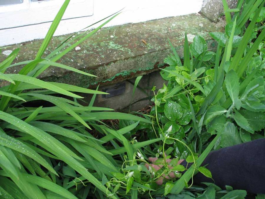
Furthermore, if the units are subsequently overgrown by shrubs then the same effects will apply since such growth, if sufficient, will curtail the wind into the units, and a result of zero or near zero wind through the units might be expected with the consequential results of extremely limited water removal.
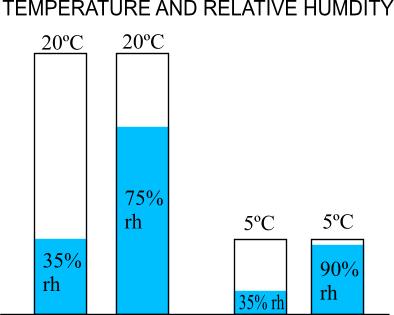
For a given temperature the relative humidity expresses the actual amount of water in the air as a proportion of the rh_picmaximum amount it could hold; the warmer the air the more water that can be held as vapour, the lower the temperature the less. This is illustrated in the adjoining diagram. At 20ºC it becomes clear that there is much more ‘space’ for water to be taken up at 35% relative humidity than at 75%; hence drying is better at the lower relative humidity. However, at 5ºC and a relative humidity of 35% there is far less ‘’space’ for air to be taken up than at 20ºC. So drying at 20ºC at 35% relative humidity is far better than at the lower temperature of 5ºC and 35%. But at a low temperature and high humidity as found during the colder months of the year, eg, 5ºC and 85 -90% relative humidity, it becomes very clear that drying conditions are very poor – there is very little ‘space’ to take up moisture.
The process of evaporation, as used by the units, is strongly governed by the relative humidity – the lower the relative humidity, the better the drying, the greater the relative humidity the slower the drying as described above. This is clearly demonstrated by the use of a whirling hygrometer where the rate of evaporation is used to determine the relative humidity, and why clothes do not dry well outside during the colder months of the year (high relative humidity).

As used in the tests undertaken by TNO the relative humidity was reported to be between 35-50% at 20-22°C. At this temperature these relative humidities are suitably low and would lead very good drying conditions (note the tests were undertaken in indoor conditions), and this is what their tests showed in the treated wall. But even when the conditions remained the same but wind simply stopped passing over the units in the test wall there was a dramatic drop in performance, ie in excess of 98%: thus wind speed is one of the key factors. graphs_1The likely cause was that water vapour evaporating from the wall collected in the units and reached humidities approaching 100% (saturation); effectively at such high relative humidities evaporation effectively stops and with no wind to ‘flush’ the units to constantly remove the water vapour build up the process stops and water is no longer abstracted from the wall. Under such conditions the rising water must therefore continue to rise up past the units.
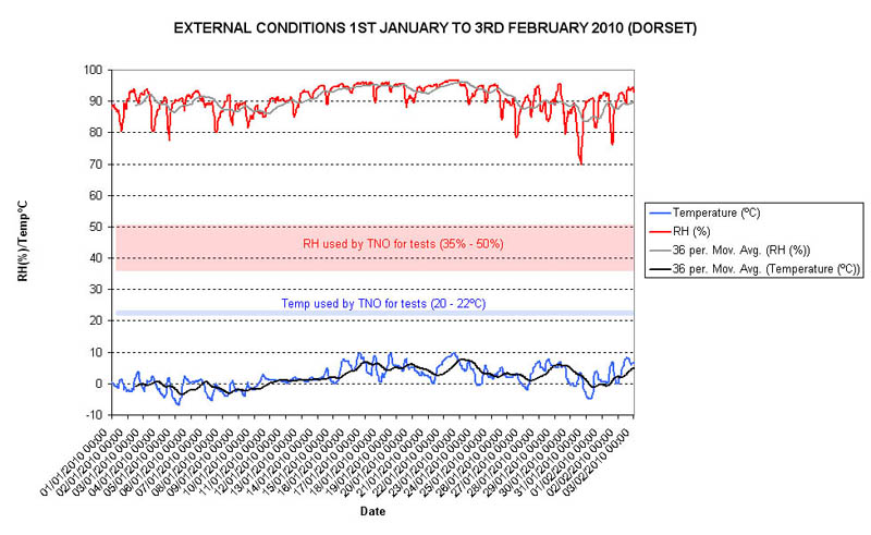
Furthermore, the conditions used for the test are not regularly achieved for any length of time in the UK especially in the colder months of the year – even in summer relative humidities externally are frequently higher than 50%, and in winter frequently remain well above 70%. As a low relative humidity is very important for evaporation then higher relative humidities reduce this process leading to sub-optimal conditions especially during the colder months of the year (see opposite) Given a property can have four sides, only two are likely to be exposed to the wind at any one time, at least two will be sheltered.
So combinations of low wind speed, low temperatures and high humidities and perhaps the wind striking the wall at a non-optimal angle would, without doubt, subject the system to long term sub-optimal conditions during which time constant and continuous sources of water ingress must simply pass by the units as under such conditions they will be incapable of operating effectively. And, like any other type damp proof course, if the rise of water is limited, their installation would not be required in the first place.
Unfortunately, the TNO did not evaluate higher relative humidities and lower temperatures to emulate conditions found in the real world environment such as those depicted in the graphs above, but in their ‘Conclusions’ the TNO report states, “The system can on the basis of the outcome of the comparative measurements, have a greater positive influence on the transportation of moisture in the wall. The system can contribute to a greater removal of moisture from wall than will be possible via the normal evaporation process. The measurements on the two test walls were carried out under laboratory conditions. In a very short period it was possible to obtain a good indication as to whether or not additional moisture was removed from wall. It is clear that the effectiveness of the system is influenced by many natural factors such as wind velocity, air humidity, temperature, etc.”
It is therefore very clear in the above statement that the investigators at TNO were aware of the influence of the natural factors of wind velocity, air humidity, and temperature which will effectively dictate the performance of the system: these are uncontrollable external environmental factors, i.e. they are uncontrollable variables which naturally change and it is these which will denigrate the performance of the system in the UK over the optimum level of performance as measured by TNO, and which they have appreciated and demonstrated. And in the real world these factors are dominant.
Finally, with reference to rising damp a paper produced in 1998 by Centre Scientifique et Technique de la Construction (CSCT, Belgium), identified, inter alia, [Google translation from French] “By definition, the effects of the above systems [the units] are limited to potentially accelerate the evaporation of water contained in the walls. These systems do not however reduce or stop rising damp. In situ tests and laboratory treatments promoting evaporation have shown questionable efficacy compared to other control systems against moisture climb” and “Used alone, this system is not in the proper sense of the word a treatment against rising damp but a process that could increase the evaporation capacity of masonry”
3.2. Condensation and the internal environment:
Warm air can hold more water as vapour than cold air, and the proportion of water that is actually present to what could potentially be held at any given temperature is known as the ‘relative humidity’.
Surface condensation is the result of moisture laden air coming into contact with a suitably cold surface. As the air is cooled the capacity of the air to hold water declines (and the relative humidity therefore increases) until at a specific temperature, depending on conditions, it cannot hold the excess of water now present; the excess water now drops out of the air as condensation onto the cold material/surface.
It is imperative to understand (1) the excess water vapour in the internal environment responsible to surface condensation is not derived from damp floors or walls (see note 1 below), and (2) the excess internal water vapour is the result of occupation (‘lifestyle’) including, washing, cooking, bathing, breathing, etc. Thus the excess water vapour is generated constantly within the property as a normal part of occupation, up to around 15 litres (nearly 4 gallons) being produced by a family per day. Wet/damp walls are not required for surface condensation to occur and indeed it occurs mostly on dry walls and as such it is very much restricted to the surface, frequently not penetrating more than a couple of millimetres on permeable surfaces, and on paint films and vinyl paper and other less permeable finishes it will remain distinctly on the surface; it does not lead to dampness through the whole thickness of the wall like rising damp.
It should also be noted that there is usually more water vapour in a building than outside simply due to that produced through occupation: water vapour exerts a pressure, the greater the amount of water vapour present the greater the vapour pressure. Water vapour moves down its pressure gradient, that is from inside the building to outside – this passage of vapour to the outside is via cracks/crevasses around windows/doors, open windows, through vents, fans, etc. It moves freely without any resistance to such movement via the above from inside the building to outside. However it will also move through the fabric of the building, ie, walls.
Water vapour moving out by open windows, fans, crevices gaps is offered no practical resistance in its movement from inside to out, that is via air to air movement (BS 5250:2002). However in order to pass through a masonry wall it has to move first through paint films, wallpaper, plaster, render, brick/stone, depending on construction, before reaching outside. These materials each offer a considerable resistance to the movement of water vapour and added together this resistance through the wall is extremely high in relation to simple air to air ventilation by opening windows or use of a fan, etc.(BS 5250:2002). Thus water vapour moves extremely slowly through a masonry wall.
In considering the TNO setup, the system as shown in the figure above is effectively a ‘sealed’ system, that is the environment within the laboratory facility has little if any access to the isolated chamber/cavity. Thus all the excess water vapour in the cavity and the isolated chamber is effectively generated solely and directly by moisture in the test wall, this moisture being significantly retained in these environments by the sealed system. What is happening is that dampness in the test walls is effectively governing the relative humidity and moisture in the isolated chamber and the cavity; there is extremely limited influence from the laboratory environment. In an occupied property the situation is reversed in that it is water generated from internal activities (see above) that governs the relative humidity/moisture vapour in the room, not dampness in a wall (even if it was to be damp in the first place – see note 1 below)
Thus, the laboratory set up does not at all reflect the real world situation where (1) even if a wall was damp/wet the water vapour from that source adds no appreciable amount to the internal environment (see note 1 below), and (2) if the wall was dry, as in most cases, no water whatsoever will be added to the interior. Thus wet or dry walls make no appreciable difference to the internal water vapour and the associated relative humidity in an occupied property.
In the case of the test walls any water in the wall is evaporating into a isolated very small volume chamber; this is rather like putting a wet rag into a small sealed plastic box, the moisture in the rag governing the moisture within the sealed box, whereas if left in an open room it would have no practical influence.
However, the isolated chamber is estimated to be around a quarter of the cubic metre (probably less) in volume. Compare this with an average room of around 50 cubic metres and with doors opening and closing, possible draghts around windows, fireplace, etc. In the test setup the surface from which water is evaporating is estimated to be around 0.5 sq metres, and this is evaporating into around 0.25 cubic metres, ie, a surface to volume ratio of 2 : 1. In a room 5m x 4m with damp rising to 1 m then we have an evaporative area of say 18 square metres evaporating water into 50 cubic metres, ie, a surface to volume ratio of 1 : 2.8; a substantial difference from the laboratory set up. Thus, the design of the experimental setup has a much greater influence than in a real world room even with rising damp with no ventilation. Also bear in mind, that unlike the TNO setup, the direction of movement of water vapour in a building is from inside to out.
The TNO test setup is actually very akin to that for checking dampness in floor/walls where a very small isolated chamber is set over the floor (or wall) to isolate and trap any minor water vapour being evaporated should the structure be damp – any accumulation of water vapour under in the small chamber is measured (British Standard 8201, Building Research Establishment Digest 163). Dampness in floors/walls cannot be assessed by measuring the relative humidity in the room as a whole since the sheer volume of water production by occupation would simply swamp the rate of loss of water from the substrate (See note 1). Also consider that relative humidity is a function of temperature and water vapour (see the figure in Section 3.1 above)

Thus, what the TNO have simply shown is that the water vapour/relative humidity in a very stagnant confined, unventilated area against a damp substrate is almost totally governed by that dampness. They have not shown, nor do they even suggest, that the units will remove water from a room where water vapour is being continuously generated via occupation. Of course, if the wall was dry as it is in almost all cases of condensation, then the test would have shown nothing whatsoever!
However, as stated previously, it is important to understand that water vapour in a property is being continuously produced by ‘occupation’ (cooking, washing, etc); the figure opposite shows this movement. Water vapour is circulating in the room and passing down its pressure gradient where it will first come into contact with the inner surface of the whole exposed face of the wall (dry or damp) before very slowly passing through to the units set in the outer face; away from the unit it will simply continue to pass through the wall. In its passage through the wall it is very likely to pass through paint films, wallpaper, plaster, render and brick before reaching the units all of which act as a partial vapour control layer distinctly slowing down the movement. Thus any water vapour is only extracted after passing into the wall and towards the outside should it enter the unit, and not before. Furthermore water vapour entering the wall away from the units will simply continue slowly to pass through the wall, the units only being to remove water vapour locally where positioned. It is now clearly evident that the units inserted as shown will have no influence whatsoever on internal moisture production or its removal directly from where it is produced. This also means that if the surface of the wall is sufficiently cold water will condense on it well before such moisture laden air reaches the units.
The system as tested by TNO and described in the Patent cannot influence internal moisture production in a property and relative humidities/condensation, and indeed, there is no claim in either of these documents that it will do so. Furthermore basic physics dictates this is the case.
Finally it is interesting to note that unlike the test in relation to ‘rising damp’ that neither the ‘Conclusion’ or content of the TNO report, or the European Standard make any reference/ comments to the units lowering relative humidity/water vapour within a property or the units use as condensation/relative humidity control in occupied buildings.
4. SUMMARY AND OPINION:
Based on the independent TNO report and considering some basic physics and the origin and movement of water and water vapour in buildings then the following questions can be answered:
Question: Do the units abstract more water from a damp/wet wall that than one without such units?
Answer: Yes, this was demonstrated by the TNO investigation albeit under some conditions this may be very minimal, and it is also what is claimed in the European Patent.
Question: Does the system stop/control rising damp?
Answer: Its performance is totally governed by external environmental factors – wind speed, wind direction, temperature and relative humidity. This was demonstrated and commented upon by TNO. Indeed, their data showed that even under optimum conditions simply by stopping the wind the performance of the system declined by over 98%. In the UK wind speed, directions, temperatures and relative humidities are far more adverse to the system over a year than the optimum used by TNO (the influences of such factors were recognised by the Dutch laboratory); this would inevitably substantially reduce the efficacy of any installed system. The performance of such systems in relation to rising damp is also questioned in the Belgian paper. At best the units might afford some degree of intermittent control of rising water, at worst very little.
Question: Can the units cure/eliminate internal surface condensation?
Answer: No. There is no evidence produced in the TNO report that they will cure/ eliminate surface condensation in domestic buildings. The report makes no comment whatsoever on this matter in either the body of the report or the conclusions. Furthermore the Patent does not make any such claim or suggest it. Simple basic physics and consideration of moisture generation and its movement in buildings dictates that the units will have no effect whatsoever on surface condensation in domestic environments. Set towards the outer part of walls they exert no influence on the factors which lead to surface condensation in buildings, ie, internal moisture production as a result of occupation activities..
Question: Can the units lower the internal relative humidity and provide a drier internal environment?
Answer: No. There is no evidence produced in the TNO report that they will make any difference to the conditions in the internal environment. The report makes no comment whatsoever on this matter in either the body of the report or the conclusions. Furthermore the Patent does not make any such claim or suggest it. Simple basic physics and consideration of internal moisture generation in buildings dictates that the units will have no effect whatsoever on the internal environment of an occupied building (also see note 1 below). Set towards outer parts of walls they exert no influence on the internal environmental conditions/water production through occupation, the source of water for high internal humidities/condensation, and as such their installation cannot lead to a drier internal environment.
Question: Are the units the complete solution for rising damp, penetrating damp, condensation and any combination of these?
Answer: No.
[Note 1. The origin of the water contributing to a condensation problem within a building is almost always from ‘occupancy activities’, ie, cooking, washing, breathing, lack of ventilation, intermittent or inadequate heating, etc. Moisture in damp walls, floors, etc, is not considered to be a significant contributory factor to the internal atmospheric water burden of a property because the water vapour arising from such sources is usually insignificant in comparison to that arising from normal household activities. Indeed, research undertaken at Building Research Establishment, East Kilbride (C.H.Sanders – unpublished data – 6/2/01; and now published in ‘Understanding Dampness’ BRE Publication 2004) showed that the amount of water lost from a saturated floor slab was around 36g per day for a floor area of 8 m2 for still air conditions (this would only increase slightly for the minimal air movement around walls). This would compare with up to 9,500g per day produced by a single individual and up to 15,000+g by a family undertaking normal household activities, eg, cooking, breathing, bathing, washing, etc: damp walls should behave no differently. Thus water vapour losses from capillary bound water in walls is therefore of little significance, and even less where dense renders, paint films and vinyl based wallpapers further reduce evaporation. Water from such sources therefore adds a negligible amount to the overall internal moisture burden of the property; in practical terms it can be discounted.
An interesting case study of this system installed to a property in Trowbridge Wiltshire.
A couple purchased this system as they were told no re-plastering was necessary, this is very desirable considering how much work this involves.
The system was installed and they were told they would get a free check to show the system is working in a years time. The damp problems never really got any better, when the year was up they were told the walls were drying down….obviously these people trusted this company.
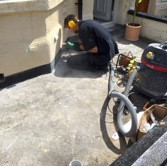
However 3 years down the line we were called in to see what was going on, the walls were visibly damp up to around 1 meter in height with high damp readings on the meter throughout the ground floor. It was discussed that this system has shown to have many faults, and I have personally seen a fair few issues to say the least.
The below pictures shows a black band at the base of the wall, this is a modern render touching the floor, this is also stopping any evaporation of rising dampness from the wall. Our technician is cutting this back neatly for removal of the render at low level to create wall base evaporation.
The below picture shows the bridging render being removed.
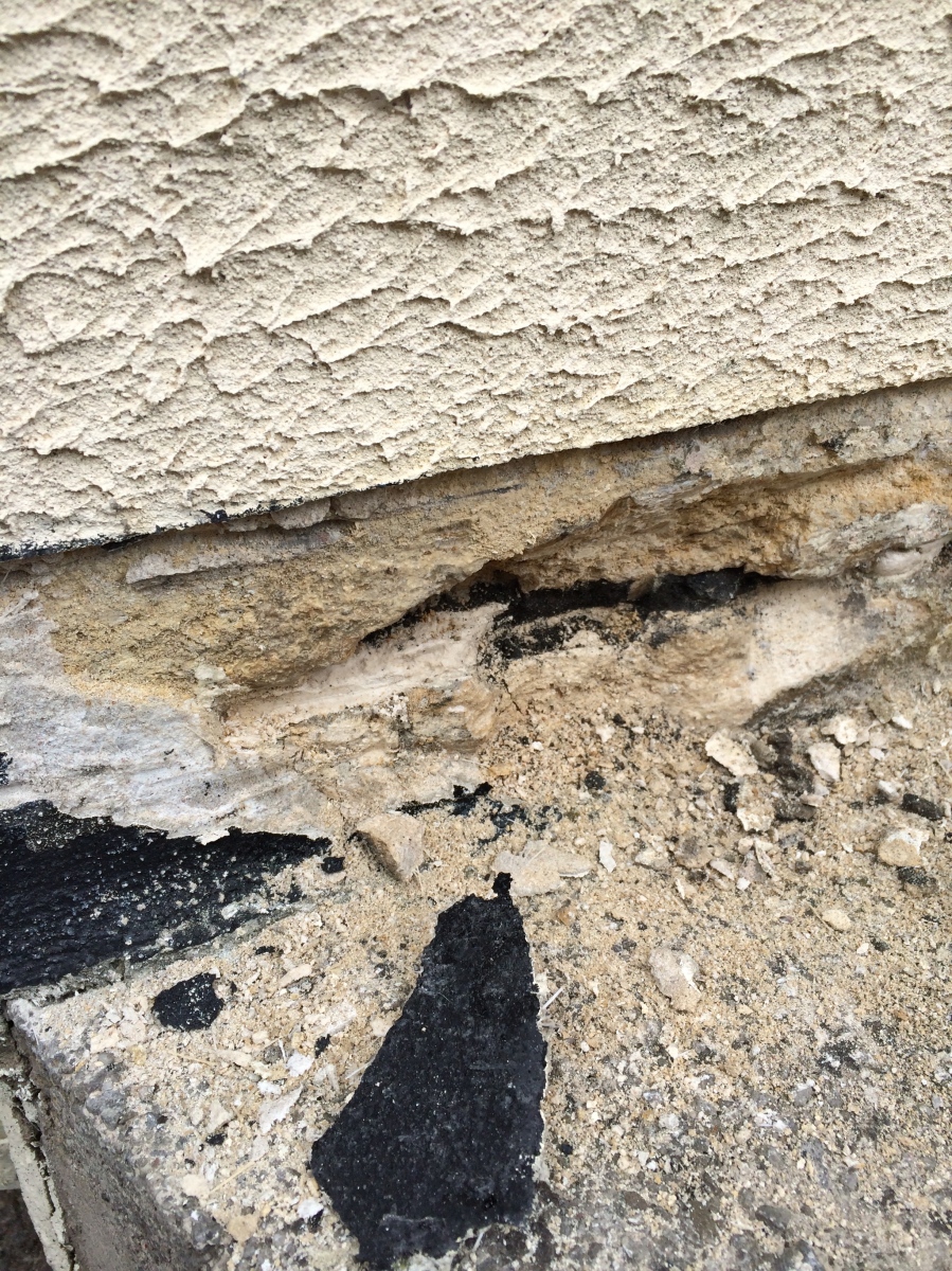
A small bell mouth was made to ensure rainwater will drip away from the building fabric, this has exposed the stone.

The render was also removed on the flank wall, and a bell mouth was also introduced.

The above pictures show very basic procedures that should have been carried out before the magic air vents should have been installed. In fact there was no need for the magic air vents that cost £3000.00.
We produced laboratory analysis following the methodology in BRE Digest 245 to prove the system wasn’t working, and that there was still rising dampness issues along with salt contaminated plaster. We worked on the principal that it was misrepresentation as they stated that no re-plastering was necessary, and fortunately my client received a full refund.
An interesting statement in their terms and conditions
7.2 In the below states that they will be measuring the brickwork for a reduction in relative humidity with a conductivity moisture reading machine (damp meter), I have never seen a damp meter that does this in conductivity mode!!!
In the report I was shown there were no conductivity meter readings so there was no way to show that the wall had dried down anyway. They also had never drilled a hole in the brick to measure relative humidity, or on the re-visit, so how could they show the wall has dried down?

Below are some of interesting pictures regarding these magic vents
The below picture shows where there has been 2 x chemical damp proof courses installed along with magic air vents, when we were called into the property it was suffering from condensation and not rising damp. This owner had spent thousands of pounds and all they needed was simply a system 3 ventilation system installed compliant with Part F of Building Regulations.

The below picture is actually the worse one I have ever seen installed, it is on an internal wall. The lady was told as she lets her dog out many times a day the wind from opening the door will contribute to it-so it will work.

The below picture shows a barn conversion with 3 x modern pvc damp proof courses cut into the wall along with a later installation of the magic vents. The plastered finish was still damp because of the hygroscopic salts, unless these are removed the decorative finish will stay visually damp.

Please remember there appear to be many of these magic wall vents systems flooding the market now, and all advertised under slightly different names. What you have to remember with most rising damp issues, the hygroscopic salts in the wall plaster are actually the visible issue. These bricks will not remove the hygroscopic salts in the plaster, so if you don’t want visibly stained plaster this will have to be removed, which is something they don’t tell you about. I have tried smoke tests on these in the wind, and also tried to cause condensation to see it they reach dew point for it to run out……I could never achieve condensation. Everybody I know that has surveyed buildings with these have never seen these with condensation running out. I was involved in job last year where somebody had these installed to a house they purchased. What the building surveyor didn’t realise, and the previous homeowner was that this actually voided the cavity wall insulation guarantee. So if wish to buy a property which has had the magic vents installed be careful. As you can imagine my client had to pay to have all the cavity wall insulation extracted, and then the magic bricks removed, along with new cavity wall insulation installed. This was a very expensive unforeseen expense.
I have also seen these cause damp to actually penetrate into the inner skin of the wall, as the duct is installed horizontal instead of a fall to the outer wall.
The magic damp removing air brick
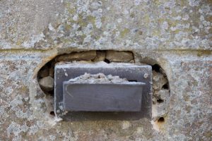
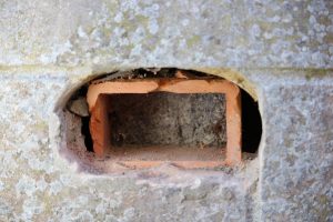
You can see the duct is bang on level and horizontal, so if any rain does penetrate the outer cavity wall it will run towards the inner skin. When this does happen damp will appear on the decorative surface.
The below video shows where the air bricks were installed to a property and failed to fix the damp issues. You can also see clearly with thermal imaging why they got mould issues to the wall internally opposite the air bricks as there was a massive cold bridge. You can also clearly see many building defects as to why the wall was suffering from rising damp issues. Typically these bricks are installed in 1 or 2 days normally at a cost of £2500.00 – £3000.00.
If you have a damp issue, make sure the damp survey is carried out by a competent person, and that all potential causes are eliminated, along with mortar/plaster sampling (gravimetrics) following the methodology in BRE DIGEST 245. I have plenty of info regarding damp surveys on my blog posts, so you can do your research on the right questions to ask a surveyor.
If you need help with a damp survey you can contact us enquiries@completepreservation.co.uk